
Why Choose an Electric Damper Actuator?

Why choose an Electric Damper Actuator? The answer begins with control, not fashion. In a commercial air-handling unit, a small actuator moves damper blades precisely, adjusting airflow as room conditions change. That movement can reduce unwanted ventilation, pressure instability, and heating or cooling waste.

The International Energy Agency reports that buildings consume about 30% of global final energy and create approximately 26% of energy-related emissions. HVAC systems represent a major share of that demand, according to the IEA’s Energy Efficiency 2023 report. An Electric Damper Actuator supports more responsive ventilation control than manual adjustment. It can accept signals from thermostats, building management systems, sensors, or fire-safety controls. Some models provide position feedback, spring-return operation, and low-power performance.

Energy-efficiency specialist Steven Nadel has stated, “Energy efficiency is the cheapest, cleanest, and fastest way to meet our energy needs.” His observation applies strongly to damper automation. Yet the actuator is not a magic switch. Poor sizing, incorrect torque selection, leaking dampers, or weak commissioning can erase expected savings. That uncomfortable detail matters.

A well-selected Electric Damper Actuator offers repeatable positioning inside dusty mechanical rooms and crowded ceiling spaces. It can react when occupancy changes, outdoor air rises, or a filter becomes restricted. The result may be quieter, steadier airflow and better temperature control. However, performance depends on the complete system. Engineers should verify damper seals, control sequences, fail-safe requirements, and maintenance access before installation. The best choice is practical, measurable, and slightly less impressive than marketing promises.
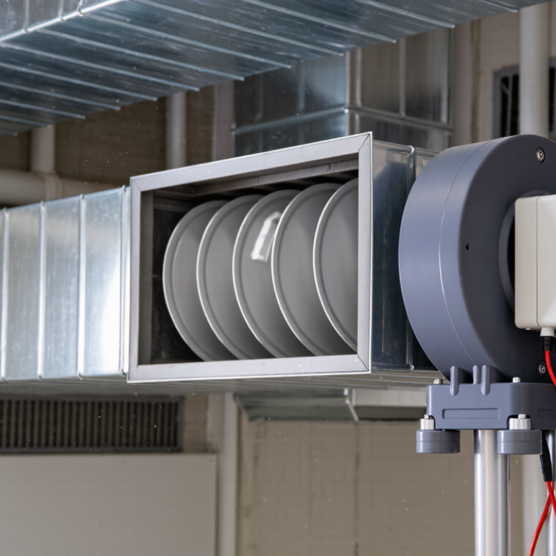
Why Choose an Electric Damper Actuator?

Electric Damper Actuators: Definition, Components, and Control Logic

Electric damper actuators control airflow by rotating a damper blade inside a ventilation duct. They convert electrical energy into precise mechanical movement. In practice, technicians select them for stable control, easier wiring, and reliable operation in hard-to-reach areas.

The main components include a motor, gear train, drive shaft, housing, position sensor, and control circuit. Some models include a spring-return mechanism for power-loss protection. The actuator may receive an on-off, floating, or proportional signal, such as 0–10 V. A feedback signal can report the actual blade position to the building control system. Small details matter. A weak shaft connection can cause inaccurate airflow.

Control logic links sensors, setpoints, and actuator movement. A temperature or pressure sensor sends data to the controller. The controller compares measured conditions with the target value. It then opens or closes the damper through a defined output signal. For example, rising duct pressure may command a damper toward a narrower position. Deadband and timing limits help prevent constant hunting. Without them, the motor may move too often.

Electric actuators offer responsive adjustment and useful diagnostic feedback. They also support automated ventilation schedules. However, correct torque sizing remains essential. I have seen systems perform poorly because the actuator was selected from damper size alone. Dirt, blade friction, and airflow pressure must also be considered. The logic can look perfect on paper. Real equipment may disagree.

Why HVAC Efficiency Matters: Buildings Use About 40% of U.S. Energy (DOE)

Why Choose an Electric Damper Actuator?

Why HVAC Efficiency Matters: Buildings Use About 40% of U.S. Energy (DOE)

Buildings use about 40% of U.S. energy, according to the U.S. Department of Energy. That figure makes airflow control more than a maintenance detail. In offices, schools, and hospitals, poorly controlled dampers can push conditioned air into empty rooms. The result is wasted heating or cooling, plus uneven comfort near windows and interior zones. Small losses repeat every hour.

An electric damper actuator moves the damper from a control signal. It can respond to thermostats, building automation systems, occupancy schedules, or air-quality sensors. When properly sized and commissioned, it helps supply only the airflow a zone needs. That can reduce unnecessary fan work and limit simultaneous heating and cooling. Technicians should verify torque, linkage alignment, stroke range, and fail position. A loose connection can defeat an excellent control strategy.

Energy savings are not automatic. A tight building envelope, clean filters, balanced ducts, and accurate sensors still matter. In retrofit work, access is often awkward, and control points may be poorly labeled. Equipment records can be less reliable than the equipment itself. That is an uncomfortable detail. Testing each damper during occupied and unoccupied modes exposes faults early. The best choice depends on load, voltage, response time, noise limits, and maintenance skill. An electric actuator earns its value when measured airflow and energy data support the decision.

Electric vs. Pneumatic Actuation: Compare Response, Wiring, and Maintenance

Why Choose an Electric Damper Actuator?

Electric and pneumatic actuators behave differently at the damper. Electric models receive power and a control signal through wiring, enabling direct positioning without compressors, air dryers, or control tubing. Response is usually predictable, but speed depends on motor torque, stroke length, and load. Pneumatic actuators can move rapidly, especially in large air-handling systems, yet their response changes with tubing distance, supply pressure, and relay adjustment. The ASHRAE Handbook identifies these factors as important influences on pneumatic control performance.

Wiring is simpler to inspect than an air network with multiple leak points. An electric actuator may need two power conductors and a feedback or communication pair. That can reduce installation time in compact mechanical rooms. However, designers must calculate voltage drop and provide a safe response during power loss. This is where electric selection becomes less straightforward.

Maintenance often favors electric actuation. The U.S. Department of Energy reports that compressed-air leaks can waste 20–30% of compressor output. Filters, regulators, dryers, and tubing also require periodic attention. Electric actuators still need inspection, especially for loose terminals, condensation, and mechanical binding. They are not maintenance-free. In my field experience, a neglected damper link can defeat even a well-designed control system. The comparison is not perfect, but lifecycle planning usually reveals the real difference.

How Torque, Modulation, and IP Ratings Guide Actuator Selection

Why Choose an Electric Damper Actuator?

Selecting an electric damper actuator is not only about opening and closing. Torque, modulation, and enclosure protection determine real-world performance. The U.S. Department of Energy reports that HVAC systems can represent nearly 40% of commercial building energy use. Small control errors can therefore become expensive.

Start with torque. Measure the damper’s breakaway torque, blade friction, and pressure load. Add a practical safety margin, but avoid excessive sizing. An oversized actuator may cost more and respond poorly. For variable airflow, choose proportional modulation rather than simple two-position control. Modulating actuators support smoother temperature control and can reduce hunting around the setpoint. ASHRAE guidance emphasizes accurate airflow control as part of efficient HVAC operation. Field conditions can still differ from calculations.

IP ratings guide enclosure selection. IEC 60529 defines protection against dust and water, but an IP rating does not guarantee chemical resistance or outdoor durability. IP54 may suit a sheltered mechanical room. Exposed equipment may require stronger protection, depending on rain, washdown, and installation details. This part is often underestimated.

Tips: Verify required torque at the damper shaft, not only from catalog estimates. Check the control signal, fail position, running time, and ambient temperature. Inspect linkage alignment during commissioning. A well-rated actuator can still fail when installation is rushed. That is the uncomfortable lesson.

Why Choose an Electric Damper Actuator? - How Torque, Modulation, and IP Ratings Guide Actuator Selection
Selection Dimension What to Check Typical Data or Range How It Guides Selection Practical Recommendation
Operating Torque Torque required to move and hold the damper under the actual airflow, pressure, temperature, and installation conditions. Common electric damper actuator sizes are often specified from approximately 2 Nm to 40 Nm; larger industrial dampers may require higher torque. Select an actuator whose rated torque exceeds the damper manufacturer's calculated breakaway and running torque.
Torque Calculation Damper size, blade design, shaft friction, air pressure, seals, temperature, and linkage efficiency. Required torque is not determined by damper area alone. A dirty filter, high differential pressure, or tight seal can increase resistance. Prevents undersizing, stalled motors, incomplete closure, and premature actuator wear.
Control Type Whether the damper needs simple open/close operation or continuous positioning. Two-position Three-point floating Modulating Two-position control is suitable for isolation or changeover. Modulating control is suitable for airflow, pressure, or temperature regulation.
Modulation Signal Compatibility between the actuator input and the building or process control system. Common analog control signals include 0–10 V DC and 2–10 V DC. Floating control uses separate open and close commands. Matching the signal prevents control instability, incorrect positioning, and integration problems.
Position Feedback Whether the control system needs confirmation of actual damper position. Feedback is commonly provided as a proportional voltage signal, such as 2–10 V DC, or through auxiliary end switches. Useful for monitoring, alarms, commissioning, energy management, and verifying fail-safe operation.
Running Time Time required for the actuator to travel from fully closed to fully open. Typical HVAC electric actuators may provide approximately 30 to 150 seconds for a 90-degree rotation, depending on the model and load. Fast travel supports quick isolation; slower travel can provide smoother control and reduce abrupt airflow changes.
Fail-Safe Function Whether the damper must move to a defined position after power loss. Spring-return actuators typically drive the damper to a preset safe position when electrical power is removed. Non-spring-return actuators generally remain in their last position. Fail-safe operation can help protect equipment, maintain smoke-control sequences, or limit airflow during a power interruption.
Enclosure Protection Protection against dust and water as defined by the IP Code under IEC 60529. IP20: basic indoor protection
IP44: protection against solid objects above 1 mm and splashing water
IP54: limited dust ingress and water splashes
IP65: dust-tight and protected against water jets
The required IP rating depends on the installation environment, cleaning method, condensation risk, and exposure to moisture or dust.
Ambient Temperature Operating temperature range at the actuator location, including heat from nearby ducts or equipment. Many HVAC actuators are designed for approximately -30°C to +50°C, although the allowable range varies by construction and application. Temperature outside the rated range can reduce torque, shorten service life, or damage electronics and seals.
Power Supply Voltage, frequency, current, and available control-panel capacity. Common supplies include 24 V AC/DC and 100–240 V AC, depending on the actuator design. Correct power compatibility supports reliable starting, accurate modulation, and safe installation.
Shaft and Mounting Compatibility Damper shaft shape, shaft diameter, rotation angle, mounting orientation, and available space. Common damper rotation is 90 degrees. Actuators may support round or square shafts within a defined diameter range. Mechanical mismatch can cause slipping, excessive side loading, restricted travel, or inaccurate positioning.
Duty Cycle How frequently and continuously the actuator will move. On/off applications may have infrequent movement, while modulating applications can operate continuously or cycle many times per hour. Frequent modulation generates more thermal and mechanical stress than occasional positioning.
Manual Override Whether the damper must be positioned during commissioning, maintenance, or a power outage. Common options include a manual release button, hand crank, clutch, or mechanical override mechanism. A manual override can simplify service work but must not defeat required safety or fire-control sequences.
Application Fit The role of the damper in the system. Air-volume control Isolation Fresh-air intake Exhaust Pressure control Application type determines the required torque, control accuracy, response time, fail position, and enclosure protection.

Verify Damper Performance Using AMCA 500-D and IEC 60529 Standards

Why Choose an Electric Damper Actuator?

Verify Damper Performance Using AMCA 500-D and IEC 60529 Standards

An electric damper actuator offers controlled movement, repeatable positioning, and easier integration with building controls. Yet actuator selection should begin with verified damper performance, not marketing claims. AMCA 500-D provides recognized methods for testing damper airflow resistance, leakage, and operational behavior. These results help engineers compare performance under defined pressure conditions.

During a proper test, technicians record pressure, airflow, blade movement, and leakage values. A damper that closes smoothly in a workshop may behave differently under system pressure. That detail matters. Test reports should identify the damper configuration, test conditions, instruments, and calibration status. Without those details, the numbers become difficult to trust.

IEC 60529 addresses enclosure protection through IP ratings. The rating indicates resistance to dust and water entering the actuator enclosure. It does not confirm airflow performance or mechanical durability. In a dusty mechanical room, the selected IP level should match actual exposure. In my field, I have seen specifications copied without checking installation conditions. That is an avoidable weakness. Review the test evidence, mounting position, wiring entries, and maintenance access together. A sealed enclosure can still fail when cable glands are poorly fitted. Small installation details often decide whether measured performance survives real service.

WhatsApp